IR Sensor Module
Hi! I hope you are doing well. We will be building a test circuit for an IR sensor in this blog. You will learn a little bit about IR sensors and how to program it with the help of Arduino.
How ir sensor work?
Absortion depends on the color of the objects. While it works quite well with all colors except for black colored objects, the color absorbs all of the infrared light, so we cannot able to detect the object but we can use this disadvantage as an advantage in some applications such as line follow robot, speedometer,color sensor and many more.
In Void setup, the code run once then set the LED as an OUTPUT and the IR sensor as an INPUT, because we are receiving information from the IR sensor after that, begin serial communication at 9600 baud.In the void loop, the code iterates over and over again.
A digitalRead function which reads the value from an IR sensor and stores it on a variable called isValue, either it's HIGH or LOW.
As a default, the sensor output is HIGH, but when the IR sensor detects anything, the output goes LOW and the led will light up along with the message "Object is detected!" which is print on serial monitor. Otherwise, it will display "No Found" and the led should be off.
The code waits every 200 milliseconds each time it runs.
ir sensor test
arduino sensor test
how to test sensors
What is ir sensor module?
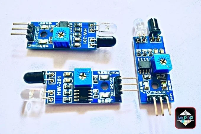
One of the most common types of sensors, the infrared sensor, is used for a variety of applications, such as, object avoidance, security systems and many more. Sensors consist of two leds, one of which is an infrared diode (IR receiver) and the other one is an infrared photodiode (IR transmitter). They can be used to measure the temperature of an object as well as detect motion.
How ir sensor work?
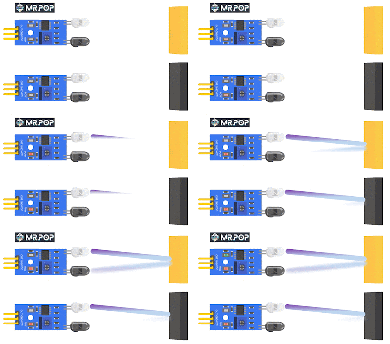
The working of ir sensor module is pretty much simple. A photodiode transmits an infrared signal when it is reflected by an object. The reflected light is partially absorbed by the object and the remaining light is returned to the receiver of the infrared diode this cause change in input voltage. This is the way we can detect the distance and the object.
 |
| Working of ir sensor |
Absortion depends on the color of the objects. While it works quite well with all colors except for black colored objects, the color absorbs all of the infrared light, so we cannot able to detect the object but we can use this disadvantage as an advantage in some applications such as line follow robot, speedometer,color sensor and many more.
Note: By adjusting its potentiometer, we can increase or decrease the distance of the IR sensor.
IR sensor module specification:
| IR sensor | Values |
|---|---|
| 1. Operating Voltage | 3.3v to 5v DC |
| 2. Operating Current | 20mA |
| 3. Adjusting Distance Range | 2 to 15 cm |
| 4. Detection Angle | 35 ° |
| 5. Dimension | 3.1CM * 1.5CM |
Aplication of IR sensor module:
2. Use as a Speedometer.
3. Security system.
4. Flame detector.
5. Color sensor.
IR sensor module Pinout:
IR sensor pin description:
| Pins | Description |
|---|---|
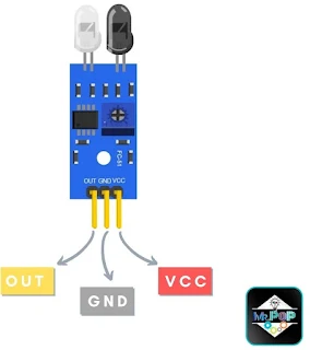
| 1. OUT | Receiving sensor value as a output. |
| 2. VCC | That's the power supply for an IR sensor. |
| 3. GND | Ground is where the voltage level is 0v. |
Component Requirements:
1. The Arduino Uno is the brian of the projects.
2. IR sensor is use to detects an object.
3. LEDs are used as indicators.
4. A resistor of 220 ohm is used to protect the led from high currents.
5. The jumper wire and breadboard are used to make the connection.
ir sensor circuit diagram:
 |
| IR sensor circuit diagram with arduino |
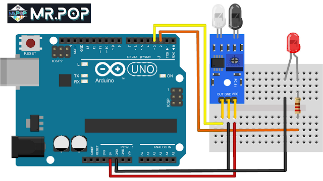
1. First, Make the connection between the ir sensor and the Arduino uno.
- The IR sensor GND is connected to pin GND of the Arduino.
- The IR sensor VCC is connected to pin 5v of the Arduino
- The IR sensor OUT is connected to pin 3 of the Arduino
3. A 220-ohm resistor should be connected to the positive pins of the LEDs. It's use to protect the LED from high currents.
- Connect the resistor end to pin 2 of the Arduino.
The circuit has now been completed.
4. Let's get started with coding.
4. Let's get started with coding.
5. Launch the Arduino IDE then copy the code from below and paste it on arduino IDE.
IR sensor code in arduino:
/*
 * Posted on https://www.mrelectrouino.com/
 * Follow us on Instagram: _mr_electrouino_
 */

int LED = 2;
int irSensor = 3;
bool isValue = HIGH;

void setup() {
  pinMode(LED, OUTPUT);
  pinMode(irSensor, INPUT);
  Serial.begin(9600);
}

void loop() {
  isValue = digitalRead(irSensor);
  if (isValue == LOW)
  {
    Serial.println("Object is detected!");
    digitalWrite(LED, HIGH);
  }
  else
  {
    Serial.println("No Found");
    digitalWrite(LED, LOW);
  }
  delay(200);
}
1. You will need a USB cable to connect the Arduino Uno to the computer.
2. Goto tool --> Board --> Arduino AVR board --> Select your Arduino board.
3. Goto tool --> port --> select your port
4. The code is now ready to be upload.
5. Once the code has been uploaded, go to the serial monitor and check the values.
2. Goto tool --> Board --> Arduino AVR board --> Select your Arduino board.
3. Goto tool --> port --> select your port
4. The code is now ready to be upload.
5. Once the code has been uploaded, go to the serial monitor and check the values.
IR sensor Code Explanation:
On the start, first we have to define the led to arduino pin 2 and the ir sensor to arduino pin 3.
Values for IR sensors are stored as boolean datatypes in the isValue variable.
int LED = 2;
int irSensor = 3;
bool isValue = HIGH;
pinMode(LED, OUTPUT);
pinMode(irSensor, INPUT);
Serial.begin(9600);
A digitalRead function which reads the value from an IR sensor and stores it on a variable called isValue, either it's HIGH or LOW.
isValue = digitalRead(irSensor);
if (isValue == LOW) {
    Serial.println("Object is detected!");
    digitalWrite(LED, HIGH);
  } else  {
    Serial.println("No Found");
    digitalWrite(LED, LOW);
}delay(200); IR sensor Project Tutorial:
Arduino IR sensor controlled EYE.
Arduino line follow robot base on ir sensor.
LinKs:
arduino sensor test
how to test sensors


Post a Comment